Thermal Camera Photos of Wemos D1 Mini ESP8266 Board
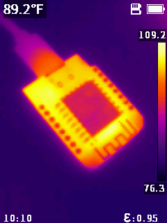
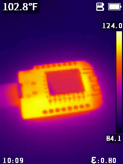
I’m not 100% sure how accurate the displayed temperatures are for the ESP8266 module itself, since using my inexpensive thermal camera I need to set emissivity manually, and the emissivity of the PCB material is substantially different from that of the main chip’s metal case.
This page suggests using emissitivy of .90 for a PCB, and this first photo was taken with .95:
This photo was taken using .80 emissitivy:
So the actual peak temperature in both photos is probably somewhere around 120ºF.
The board in these photos is powered via USB and running one of my HTTPS demos, which uses a clock speed of 160MHz rather than the default 80MHz. I’m sure this increases power usage and therefore temperature nontrivially.
While writing this quick post, I found some useful & interesting readings on emissivity:
- What Is Emissivity?
- How Does Emissivity Affect Thermal Imaging?
- A Practical Guide to Emissivity in Infrared Inspections
One of those links suggests applying black electrical tape — which has a very high emissivity — to get an accurate reading from reflective or low-emissivity objects. I’ll keep that tip in mind.


